- 您现在的位置:买卖IC网 > Sheet目录2003 > LTC1420IGN#TRPBF (Linear Technology)IC ADC 12BIT 10MSPS SAMPL 28SSOP
10
LTC1420
1420fa
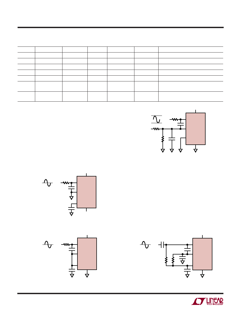
Table 2. Comparison of Analog Input Configurations
SUPPLIES
COUPLING
VREF
GAIN
AIN
+
AIN
–
COMMENTS
±5V
DC
4.096V
1×±2.048
0
Best SNR, THD
5V
DC
4.096V
2×
2.5 ± 1.024
2.5
Best SINAD, THD for Single Supply
5V
DC
2.048V
1×
2.5 ± 1.024
2.5
Worse Noise than Above Case
5V
DC
4.096V
1×
2.5 ± 2.048
2.5
Best Single Supply Noise, THD Is Not Optimal
5V
DC
4.096V
1×
0 to 4.096
2.048
Same As Above
±5V
AC
4.096V
1×±1.024
±1.024
Very Best SNR, THD
(Transformer)
5V
AC
4.096V
1×
2.5 ± 1.024
Very Best SNR, THD for Single Supply
(Transformer)
1420 F05
1F
+AIN
VSS
VIN
2.5V
LTC1420
5V
–AIN
VCM
1420 F06
+AIN
VSS
VIN
4.096V
0V
5V
2.048V
LTC1420
5V
–AIN
SENSE
Figure 4. DC Coupling a Ground
Centered Signal (Dual Supply System)
Figure 5. DC Coupling a Signal Centered
Around 2.5V (Single Supply System)
Figure 6. DC Coupling a 0V to 4.096V Signal
1420 F07
+AIN
VSS
VIN
1F
0V
C
RR
LTC1420
5V
–AIN
VCM
Figure 7. AC Coupling to the LTC1420. Note That the Input Signal
Can Almost Always Be Directly Coupled with Better Performance
1420 F04
1F
+AIN
VSS
VIN
0V
LTC1420
5V
–5V
–AIN
VCM
APPLICATIONS INFORMATION
WU
U
DC Coupling the Input
In most applications the analog input signal can be directly
coupled to the LTC1420 inputs. If the input signal is
centered around ground, such as when dual supply op
amps are used, simply connect – AIN to ground and
connect VSS to –5V (Figure 4). In a single power supply
system with the input signal centered around 2.5V, con-
nect – AIN to VCM and VSS to ground (Figure 5). If the input
signal is not centered around ground or 2.5V, the voltage
for – AIN must be generated externally by a resistor divider
or a voltage reference (Figure 6).
AC Coupling the Input
The analog inputs to the LTC1420 can also be AC coupled
through a capacitor, though in most cases it is simpler to
directly couple the input to the ADC. Figure 7 shows an
example where the input signal is centered around ground
and the ADC operates from a single 5V supply. Note that
the performance would improve if the ADC was operated
from a dual supply and the input was directly coupled (as
in Figure 4). With AC coupling the DC resistance to ground
should be roughly matched for + AIN and – AIN to maintain
offset accuracy.
发布紧急采购,3分钟左右您将得到回复。
相关PDF资料
LTC1426IS8#TR
IC DAC PWM 6BIT DUAL MCPWR 8SOIC
LTC1427CS8-50#TRPBF
IC D/A CONV 10BIT W/SMBUS 8-SOIC
LTC1428CS8-50#TRPBF
IC D/A CONV 8BIT SINK OUT 8-SOIC
LTC1446LIS8#TRPBF
IC D/A CONV 12BIT R-R DUAL 8SOIC
LTC1448IS8#TRPBF
IC D/A CONV 12BIT R-R DUAL 8SOIC
LTC1450LIG#TR
IC DAC 12BIT R-R PAR MPWR 24SSOP
LTC1451IS8#TRPBF
IC D/A CONV 12BIT R-R 8-SOIC
LTC1454LCN
IC D/A CONV 12BIT R-R DUAL 16DIP
相关代理商/技术参数
LTC1421CG
功能描述:IC CONTROLLER HOT SWAP 24-SSOP RoHS:否 类别:集成电路 (IC) >> PMIC - 热交换 系列:- 产品培训模块:Lead (SnPb) Finish for COTS
Obsolescence Mitigation Program 标准包装:119 系列:- 类型:热交换控制器 应用:通用型,PCI Express? 内部开关:无 电流限制:- 电源电压:3.3V,12V 工作温度:-40°C ~ 85°C 安装类型:表面贴装 封装/外壳:80-TQFP 供应商设备封装:80-TQFP(12x12) 包装:托盘 产品目录页面:1423 (CN2011-ZH PDF)
LTC1421CG#PBF
功能描述:IC CONTROLLER HOT SWAP 24-SSOP RoHS:是 类别:集成电路 (IC) >> PMIC - 热交换 系列:- 产品培训模块:Lead (SnPb) Finish for COTS
Obsolescence Mitigation Program 标准包装:119 系列:- 类型:热交换控制器 应用:通用型,PCI Express? 内部开关:无 电流限制:- 电源电压:3.3V,12V 工作温度:-40°C ~ 85°C 安装类型:表面贴装 封装/外壳:80-TQFP 供应商设备封装:80-TQFP(12x12) 包装:托盘 产品目录页面:1423 (CN2011-ZH PDF)
LTC1421CG#TR
功能描述:IC CONTROLLER HOTSWAP ADJ 24SSOP RoHS:否 类别:集成电路 (IC) >> PMIC - 热交换 系列:- 产品培训模块:Lead (SnPb) Finish for COTS
Obsolescence Mitigation Program 标准包装:119 系列:- 类型:热交换控制器 应用:通用型,PCI Express? 内部开关:无 电流限制:- 电源电压:3.3V,12V 工作温度:-40°C ~ 85°C 安装类型:表面贴装 封装/外壳:80-TQFP 供应商设备封装:80-TQFP(12x12) 包装:托盘 产品目录页面:1423 (CN2011-ZH PDF)
LTC1421CG#TRPBF
功能描述:IC CONTROLLER HOT SWAP 24-SSOP RoHS:是 类别:集成电路 (IC) >> PMIC - 热交换 系列:- 产品培训模块:Lead (SnPb) Finish for COTS
Obsolescence Mitigation Program 标准包装:119 系列:- 类型:热交换控制器 应用:通用型,PCI Express? 内部开关:无 电流限制:- 电源电压:3.3V,12V 工作温度:-40°C ~ 85°C 安装类型:表面贴装 封装/外壳:80-TQFP 供应商设备封装:80-TQFP(12x12) 包装:托盘 产品目录页面:1423 (CN2011-ZH PDF)
LTC1421CG1
制造商:Linear Technology 功能描述:
LTC1421CG-2.5
功能描述:IC CONTROLLER HOT SWAP 24-SSOP RoHS:否 类别:集成电路 (IC) >> PMIC - 热交换 系列:- 产品培训模块:Lead (SnPb) Finish for COTS
Obsolescence Mitigation Program 标准包装:119 系列:- 类型:热交换控制器 应用:通用型,PCI Express? 内部开关:无 电流限制:- 电源电压:3.3V,12V 工作温度:-40°C ~ 85°C 安装类型:表面贴装 封装/外壳:80-TQFP 供应商设备封装:80-TQFP(12x12) 包装:托盘 产品目录页面:1423 (CN2011-ZH PDF)
LTC1421CG-2.5#PBF
功能描述:IC CONTROLLER HOT SWAP 24-SSOP RoHS:是 类别:集成电路 (IC) >> PMIC - 热交换 系列:- 标准包装:50 系列:- 类型:热交换控制器 应用:-48V 远程电力系统,AdvancedTCA ? 系统,高可用性 内部开关:无 电流限制:可调 电源电压:11.5 V ~ 14.5 V 工作温度:-40°C ~ 85°C 安装类型:表面贴装 封装/外壳:10-TFSOP,10-MSOP(0.118",3.00mm 宽) 供应商设备封装:10-MSOP 包装:管件
LTC1421CG-2.5#TR
功能描述:IC CONTROLLER HOTSWP 2.5V 24SSOP RoHS:否 类别:集成电路 (IC) >> PMIC - 热交换 系列:- 产品培训模块:Lead (SnPb) Finish for COTS
Obsolescence Mitigation Program 标准包装:119 系列:- 类型:热交换控制器 应用:通用型,PCI Express? 内部开关:无 电流限制:- 电源电压:3.3V,12V 工作温度:-40°C ~ 85°C 安装类型:表面贴装 封装/外壳:80-TQFP 供应商设备封装:80-TQFP(12x12) 包装:托盘 产品目录页面:1423 (CN2011-ZH PDF)